Boards
-
USB communication module
This is a 40x40 mm board equipped with FT2232, a dual-line USB driver by FTDI inc. This enables apparent simultaneous two-channel data communication between the OPENCORE NMR spectrometer and the console software installed on a personal computer through a single USB cable. In the current architecture of the OPENCORE NMR, the one channel (channel A) is used in the UART 232 mode for sending/receiving the commands/responses to/from the PPG interface core module built inside the FPGA chip, the other (channel B) for transferring the NMR signals from the RCVR core module to the personal computer in the 245 FIFO mode.
Before using, the mode of operation must be configured to the EPROM on the board using the MProg software (FTDI). Use this configuration file.
Also, the D2XX driver must be installed on the Windows OS, which is available from FTDI inc.
[Version 001]
USB.sch (schematic)
USB.brd (board)
Parts list:
| Part | Value | Device | Package | Description |
| C1 | *27p | C | 1608 | |
| C2 | *27p | C | 1608 | |
| C3 | 33nF | C | 3216 | |
| C4 | 0.1u | C | 1608 | |
| C5 | 0.1u | C | 1608 | |
| C6 | 0.1u | C | 1608 | |
| C7 | 10u | C | 3216 (polar) | tantalum |
| CN1 | | FH12-30S-0.5SH (HIROSE) | | 0.5 mm pitch FPC connector |
| FB | | FERRITE BEAD | 3216 | |
| R1 | 27 | R | 1608 | |
| R2 | 27 | R | 1608 | |
| R3 | 1.5k | R | 1608 | |
| R4 | 470 | R | 1608 | |
| R5 | 2.2k | R | 1608 | |
| R6 | 10k | R | 1608 | |
| U1 | | FT2232D (FTDI) | | Dual USB UART/FIFO I.C. |
| U2 | | 67068-704J (MOLEX) | | USB connector |
| U3 | | AT93C46-10TU-2.7 (ATMEL) | | Serial EPROM |
| U4 | | LM2937IMP-3.3 | SOT-223 | Voltage regulator |
| Y1 | 6 MHz | HC49/4H SMX | | 6 MHz crystal |
*Note: The proper value for C1 and C2 depends on the crystal oscillator. Check the datasheet of the 6 MHz crystal that you use.
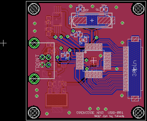
- DDS(II)
This is a 40x40 mm board equipped with AD9858, a DDS-dedicated LSI operating with a 1GHz or 2 GHz clock signal. This serves for generating frequency-tunable, phase-fixed rf signals used both for an rf transmitter and as a receiver reference signal.

[Version 03]
DDS2-02.sch (schematic)
DDS2-02.brd (board)
Parts list
| Part | Value | Device | Package | Description |
| C1 | 1000p | C | 1005 | |
| C2 | 1000p | C | 1005 | |
| C3 | 0.1u | C | 1005 | |
| C4 | 6p | C | 1608 | |
| C5 | 12p | C | 1608 | |
| C6 | 12p | C | 1608 | |
| C7 | 33u | C | 3216 (polar) | tantalum |
| C8 | 0.01u | C | 1608 | |
| C9 | 0.1u | C | 1005 | |
| C10 | 0.1u | C | 1005 | |
| C11 | 0.1u | C | 1005 | |
| C12 | 0.01u | C | 1005 | |
| C13 | 0.01u | C | 1005 | |
| C14 | 0.01u | C | 1005 | |
| C15 | 0.01u | C | 1005 | |
| C16 | 0.01u | C | 1005 | |
| C17 | 0.01u | C | 1005 | |
| C18 | 0.01u | C | 1005 | |
| C19 | 0.01u | C | 1005 | |
| C20 | 0.01u | C | 1005 | |
| C21 | 0.01u | C | 1005 | |
| C22 | 0.01u | C | 1005 | |
| C23 | 0.1u | C | 1005 | |
| C24 | 0.01u | C | 1005 | |
| C25 | 33u | C | 3216 (polar) | tantalum |
| CN1 | | U.FL-R-SMT (HIROSE) | | |
| CN2 | | FH12-30S-0.5SH (HIROSE) | | 0.5mm pitch FPC connector |
| CN3 | | U.FL-R-SMT (HIROSE) | | |
| CN4 | | U.FL-R-SMT (HIROSE) | | |
| CN5 | | DF13-2P-1.25V (HIROSE) | | |
| FB1 | | FERRITE BEAD | 1608 | |
| FB2 | | FERRITE BEAD | 1608 | |
| FB3 | | FERRITE BEAD | 1608 | |
| FB4 | | FERRITE BEAD | 1608 | |
| U1 | | AD9858 (Analog Divices) | | DDS chip |
| L1 | 12nH | L | 1608 | |
| R1 | 2k | R | 1005 | |
| R2 | 27 | R | 1005 | |
| R3 | 27 | R | 1005 | |
| T1 | | TC1-1-13M+ (Mini Circuits) | AT224 | RF transformer |
| T2 | | TC1-1T+ (Mini Circuits) | AT224 | RF transformer |
| U2 | | ADP-2-1W (Mini Circuits) | | RF splitter |
("DDS" stands for "Direct Digital Synthesis")
-
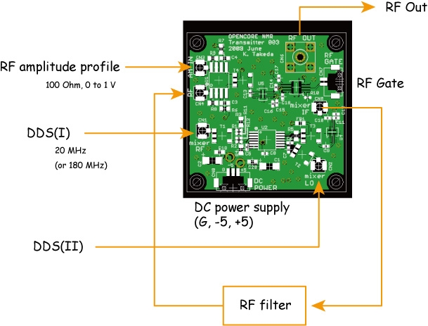
RF Transmitter
This is a 40x40 mm board for generating rf pulses. On this board implemented are a mixer (AD8343, Analog Devices) which receives a phase-tunable signal from DDS(I) and a frequency-tunable signal from DDS(II) to create a signal with the intended frequency and phase, an rf multiplier (AD834, Analog Devices) for amplitude modulation, and an rf switch (M3SWA-2-50DR, Mini-Circuits) for pulse modulation.
[Version 003]
trans003.sch (schematic)
trans003.brd (board)
Parts list
| Part | Value | Device | Package | Description |
| C1 | 33u | C | 3216 (polar) | tantalum |
| C2 | 33u | C | 3216 (polar) | tantalum |
| C3 | 0.1u | C | 1608 | |
| C4 | 0.1u | C | 1608 | |
| C5 | 0.1u | C | 1005 | |
| C6 | 0.1u | C | 1005 | |
| C7 | 0.1u | C | 1005 | |
| C8 | 0.01u | C | 1005 | |
| C9 | 0.1u | C | 1005 | |
| C10 | 0.1u | C | 1005 | |
| C11 | 100p | C | 1005 | |
| C12 | 0.1u | C | 1005 | |
| C13 | 0.1u | C | 1005 | |
| C14 | 0.1u | C | 1005 | |
| C15 | 100p | C | 1005 | |
| C16 | 0.1u | C | 1005 | |
| C17 | 0.1u | C | 1005 | |
| C18 | 0.1u | C | 1005 | |
| C19 | 0.01u | C | 1608 | |
| C20 | 0.01u | C | 1608 | |
| CN1 | | U.FL-R-SMT (HIROSE) | | |
| CN2 | | U.FL-R-SMT (HIROSE) | | |
| CN3 | | U.FL-R-SMT (HIROSE) | | |
| CN4 | | U.FL-R-SMT (HIROSE) | | |
| CN5 | | U.FL-R-SMT (HIROSE) | | |
| CN6 | | SMA STRAIGHT | | |
| FB1 | | FERRITE BEAD | 1608 | |
| CN7 | | DF13-2P-1.25V (HIROSE) | | Gate input |
| CN8 | | DF13-3P-1.25V (HIROSE) | | Power supply |
| R1 | 10 | R | 1005 | |
| R2 | 10 | R | 1005 | |
| R3 | 68 | R | 1608 | |
| R4 | 68 | R | 1608 | |
| R5 | 510 | R | 1608 | |
| R6 | 10 | R | 1608 | |
| R7 | 50 | R | 1608 | |
| R8 | 50 | R | 1608 | |
| R9 | 100 | R | 1608 | |
| R10 | 50 | R | 1005 | |
| R11 | 10 | R | 1005 | |
| R12 | 10 | R | 1005 | |
| T1 | | TC4-1W+ (Mini-Circuits) | AT224 | |
| T2 | | TC1-1-13M+ (Mini-Circuits) | AT224 | |
| T3 | | TC4-1W+ (Mini-Circuits) | AT224 | |
| T4 | | TC1-1T+ (Mini-Circuits) | AT224 | |
| U1 | | AD834 (Analog Devices) | | |
| U2 | | AD8343 (Analog Devices) | | |
| U3 | | M3SWA-2-50DR (Mini-Circuits) | | |
| U4 | | AD8354 (Analog Devices) | | |
| U5 | | AD8354 (Analog Devices) | | |
-
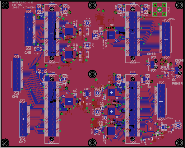
Mother board
Currently we use a commercial FPGA breadboard, ACM-202-80C8 (HUMANDATA) equipped with a Cyclone III device (EP3C80F780C8, Altera). This breadboard is to be docked with a 80x100 mm board, which we call the "mother board"
[Version 002]
mother-002.sch (schematic)
mother-002.brd (board)
Parts list
| Qty | Value | Device | Parts |
| 8 | 0.01u | C (1608) | C32, C33, C36, C37, C40, C41, C44, C45 |
| 45 | 0.1u | C (1005) | C1, C4, C7, C8, C10, C11, C16, C17, C18, C19, C22, C25, C26, C28, C29, C46, C49, C52, C53, C55, C56, C57, C60, C63, C64, C66, C67, C68, C71, C74, C75, C77, C78, C79, C82, C85, C86, C88, C89, C90, C93, C96, C97, C99, C100 |
| 1 | 0.1uF | C (1005) | C14 |
| 1 | 1k | R (1005) | R4 |
| 8 | 2k | R (1005) | R1, R5, R6, R7, R8, R11, R14, R17 |
| 2 | 10uF | C (polar, 3216) | C13, C15 |
| 1 | 20p | C (1005) | C12 |
| 2 | 33 | R (1005) | R2, R3 |
| 8 | 33u | C (polar, 3216) | C30, C31, C34, C35, C38, C39, C42, C43 |
| 14 | 33u | C (polar, 3216) | C3, C6, C21, C24, C48, C51, C59, C62, C70, C73, C81, C84, C92, C95 |
| 4 | 50 | R (1005) | R9, R12, R15, R18 |
| 4 | 100 | R (1005) | R10, R13, R16, R19 |
| 21 | 1000p | C (1005) | C2, C5, C9, C20, C23, C27, C47, C50, C54, C58, C61, C65, C69, C72, C76, C80, C83, C87, C91, C94, C98 |
| 1 | | AD9245BCPZ-80 (Analog Devices) | U7 |
| 7 | | AD9740ACPZ (Analog Devices) | U1, U2, U3, U4, U5, U6, U8 |
| 2 | | DF13-2P-1.25V (HIROSE) | CN19, CN20 |
| 46 | | FERRITE BEAD | FB1, FB2, FB3, FB4, FB5, FB6, FB7, FB8, FB9, FB10, FB11, FB12, FB13, FB14, FB15, FB16, FB17, FB18, FB19, FB20, FB21, FB22, FB23, FB24, FB25, FB26, FB27, FB28, FB29, FB30, FB31, FB32, FB33, FB34, FB35, FB36, FB37, FB38, FB39, FB40, FB41, FB42, FB43, FB44, FB45, FB46 |
| 5 | | FH12-30S-0.5SH (HIROSE) | CN5, CN6, CN7, CN16, CN17 |
| 2 | | FX10A-80S/8-SV (HIROSE) | CN1, CN2 |
| 2 | | FX10A-100S/10-SV (HIROSE) | CN3, CN4 |
| 1 | | SMA STRAIGHT | CN18 |
| 4 | | TC1-1T+ (Mini-Circuits) | T1, T2, T3, T4 |
| 9 | | U.FL-R-SMT (HIROSE) | CN8, CN9, CN10, CN11, CN12, CN13, CN14, CN15, CN21 |
-
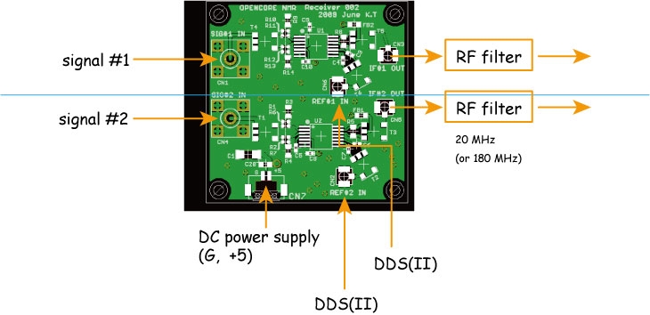
Receiver board
[Version 002]
rcvr002.sch (schematic)
rcvr002.brd (board)
Parts list
| Part | Value | Device | Package | Description |
| C1 | 33u | C | 3216 (polar) | tantalum |
| C3 | 0.1u | C | 1005 | |
| C4 | 0.1u | C | 1005 | |
| C5 | 0.1u | C | 1005 | |
| C6 | 0.1u | C | 1005 | |
| C7 | 0.1u | C | 1005 | |
| C8 | 0.01u | C | 1005 | |
| C9 | 0.1u | C | 1005 | |
| C10 | 0.01u | C | 1005 | |
| C20 | 0.01u | C | 1608 | |
| CN1 | | SMA STRAIGHT | | |
| CN2 | | U.FL-R-SMT (HIROSE) | | |
| CN3 | | U.FL-R-SMT (HIROSE) | | |
| CN4 | | SMA STRAIGHT | | |
| CN5 | | U.FL-R-SMT (HIROSE) | | |
| CN6 | | U.FL-R-SMT (HIROSE) | | |
| CN7 | | DF13-2P-1.25V (HIROSE) | | |
| FB1 | | FERRITE BEAD | 1608 | |
| FB2 | | FERRITE BEAD | 1608 | |
| R1 | 10 | R | 1005 | |
| R2 | 10 | R | 1005 | |
| R3 | 68 | R | 1608 | |
| R4 | 68 | R | 1608 | |
| R5 | 510 | R | 1608 | |
| R6 | 10 | R | 1005 | |
| R7 | 10 | R | 1005 | |
| R8 | 510 | R | 1608 | |
| R9 | 68 | R | 1608 | |
| R10 | 10 | R | 1005 | |
| R11 | 10 | R | 1005 | |
| R12 | 10 | R | 1005 | |
| R13 | 10 | R | 1005 | |
| R14 | 68 | R | 1608 | |
| T1 | | TC4-1W+ (Mini-Circuits) | AT224 | |
| T2 | | TC1-1-13M+ (Mini-Circuits) | AT224 | |
| T3 | | TC4-1W+ (Mini-Circuits) | AT224 | |
| T4 | | TC4-1W+ (Mini-Circuits) | AT224 | |
| T5 | | TC4-1W+ (Mini-Circuits) | AT224 | |
| T6 | | TC1-1-13M+ (Mini-Circuits) | AT224 | |
| U1 | | AD8343 (Analog Devices) | | |
| U2 | | AD8343 (Analog Devices) | | |
-
Gate distribution board
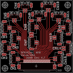
[Version 001]
gates-001.brd (board)
Parts list
| Part | | Device | | Description |
| CN0 | | FH12-30S-0.5SH (HIROSE) | | 0.5 mm pitch FPC connector |
| CN1-CN15 | | DF13-2P-1.25V (HIROSE) | | |
-
1 GHz Clock board
The DDS board (see above) needs a 1 GHz clock input. This board provides one option (you may want to bring the 1 GHz clock signal from other sources that you have). A 1 GHz clock module DPLO-1GHz (Digital Signal Technology inc.) is employed. In order to obtain the stable clock, it is important to add 10 MHz external clock option when you order this device. In turn, a stable 10 MHz clock is also required (see below).
[Version 001]
DPLO-01.sch (schematic)
DPLO-01.brd (board)
Parts list
| Part | Value | Device | Package | Description |
| | DPLO-1GHz (external clk option) | | 1 GHz CLK (http://www.dst.co.jp/en/) |
| CN1 | | DF13-2P-1.25V (HIROSE) | | |
| CN2,CN3,CN4 | | U.FL-R-SMT (HIROSE) | | |
| CN5 | | U.FL-R-SMT (HIROSE) | | |
| R1,R2,R3,R4 | 24 | R | 1608 | |
| C1 | 0.01u | C | 1608 | |
| C2 | 10u | C | 3216 (polar) | tantalum |
-
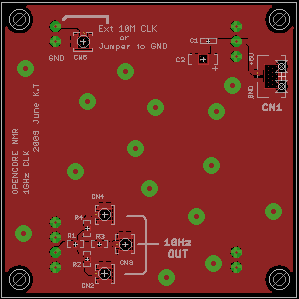
10 MHz Clock board
This board provides a clock signal at 10 MHz. The stable 10 MHz clock signal is required for the mother board and the 1 GHz clock board. Importantly, the stability of the RF signals depends on the quality of the 10 MHz clock.
 
[Version 001]
10MCLK01.brd (board)
Parts list
| Part | Value | Device | Package | Description |
| OCXO | 10 MHz | MOFH5200C-10.000 (MMD Components) | DIP14 | |
| HC04 | | 74HC04 | DIP14 | Hex inverter |
| OUT1,OUT3,OUT4,OUT6 | | SMA Straight | | |
| OUT2,OUT5 | | U.FL-R-SMT (HIROSE) | | |
| MON/EXT | | U.FL-R-SMT (HIROSE) | | |
| DC_POW | | DF13-2P-1.25V (HIROSE) | | DC power supply (5V) |
|